

Integrated storm sewage treatment plant
“ДЕКО-ЛС-МР”
ТУ 4859-023-10442696-2009
Specifications
| № | Parameters | Points of measure | ДЕКО-ЛС-МР-1,4 | ДЕКО-ЛС-МР-1,7(2,1) | ||
| before treatment | after treatment | before treatment | after treatment | |||
| 1. | Highest solids content | mg/l | 10 000 | 5,0* | 10 000 | 5,0* |
| 2. | Highest oil concentration | mg/l | 5000 | 0,05* | 5000 | 0,05* |
| 3. | Drain well surface area | hectare | as per the design (~1,4) | as per the design (~1,8 - 2,1) | ||
| 4. | Capacity | m3/hour | 1,8 – 2,2 | 1,8 – 2,2 | ||
| 5. | Overall dimensions of the plant (without chambers) | m | 10,0 х 3,0 х 3,425 | 12,0 х 3,0 х 3,425 | ||
| 6. | Mark of a frame bottom of a plant | m | from (-4,2) to (-6,2) at a pitch of 0,5m | from (-4,2) to (-6,2) at a pitch of 0,5m | ||
| 7. | Volume of storage vessel. | m3 | 65 | 80 | ||
| 8. | Weight of a plant without chambers (dry). | kg | 11 000 | 12 000 | ||
| 9. | Weight of a plant without chambers (filled up). | kg | 78 000 | 93 000 | ||
| 10 | Dimensions of the reference foundation grounds | m | 9,185 х2,53 | 11,09 х 2,53 | ||
| 11 | Allowable volume (before the compulsory unloading) of the trapped petroleum products. | dm3 | Up to 200 | Up to 200 | ||
| 12 | Allowable volume (before the compulsory unloading) of the trapped sludge. | m3 | Up to 6,0 | Up to 6,0 | ||
*Attention! The above mentioned parameters are achieved only at the compliance with all the requirements
of the process procedures.
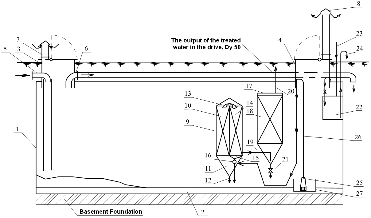
Process flow diagram
Integrated storm sewage treatment plant "ДЕКО-ЛС-МР" is used for storm sewage storage and its follow-up purification from organic impurities and petroleum products.
Integrated storm sewage treatment plant "ДЕКО-ЛС-МР" provide clearing of the specified sewage up to the indexes that satisfy the requirements of current environmental regulations, that allows to discharge sewage waters in any reservoir, in drainage systems, onto local terrain, etc. or to reuse it.
Explication
| 1 – Apparatus casing | 15 – sludge collector |
| 2 - frame | 16 – ball float valve |
| 3 - shaft | 17 – casing of the III stage of treatment unit |
| 4 - shaft | 18 – sorption chamber |
| 5 – inlet spout | 19 – inlet branch pipe |
| 6 – overflow pipe | 20 – outlet branch pipe |
| 7 – inflow pipe | 21 – discharger |
| 8 – exhaust pipe | 22 – trapped oil collector |
| 9 – unit of I-II stages of treatment | 23 – pressurised air pipeline |
| 10 – thin-layer retention pond (I stage of treatment) | 24 – trapped oil drainage pipeline |
| 11 – holding chamber | 25 – underwater sludge pump |
| 12 – recirculating discharger | 26 – outlet branch pipe |
| 13 – intermediate trapped oil collector | 27 – eduction capacity |
| 14 – chamber (II stage of treatment ) |
|
Work of integrated storm sewage treatment plant "ДЕКО-ЛС-МР" is carried out as follows:
Storm water sewage flows through the inlet spout 5 into the case 1 where the water is preliminary desilted (sludge settles, and the particles of mineral oil emerge on a surface, forming a floating film). After the filling of the case 1, the incoming storm water sewage are taken away through the inflow pipe 6 as conditionally pure into the planned discharge outlet;
As a water level in the case 1 increase, the operating float activate the pump 25, which submits water through the outlet brunch pipe 26 into the holding chamber 11, where it is divided into two streams: the main stream and the recycle stream. The main stream flows into the thin layer retention pond 10. The suspended solids trapped into the thin layer retention pond 10 settles into the holding chamber 11 and through the recirculating discharger 12 dispose (together with recycle stream) into the case 1.
Passing through the thin layer retention pond 10 the particles of oil come to the top and accumulate in the form of film internal surfaces of pipes, and (due to a difference between relative densities of water and mineral oil) move upwards. Further they come off a film in a form of larger drops and are taken out by the basic stream to the chamber 13 where they collect in the top part in the form of a floating film. After the thin layer retention pond 10, partially treated water, flows into the chamber 14, where the subsequent treatment is carried out.
Minor particles of mineral oil which have not integrated in thin layer retention pond 10, moving between floating granules, touch them and pass as a film to their surface. As a thickness of a film increase, mineral oil pass (due to a difference of relative densities) in a film of above granules and, finally, emerge in the form of large drops in a floating film of the chamber 13.
Simultaneously to integration of fine drops of mineral oil it takes place an integration of fine fractions of the suspended solids which settle in the sludge collector 15.
Final deep water treating is carried out in sorption chamber 18, whence water is taken away through the outlet branch pipe 20 and the planned connected brunch pipe into the water pond, onto local terrain or to the water-storage tank for recycling.
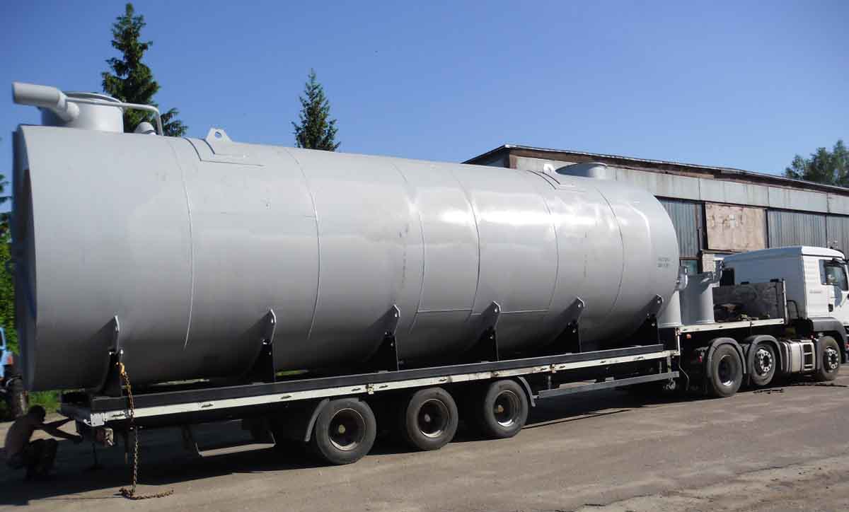
Shipment of a plant "ДЕКО-ЛС-МР-1,4"
on truck (oversize)
Designation when order (example):
Integrated storm sewage treatment plant "ДЕКО-ЛС-МР-1,4", depth of a frame bottom is (-5,2)m.
At fall of a level of sewage in the case 1 below the certain level, the operating float switches off the pump 25. After switching off of the pump of 25 all volume of the cleared water in the clearing units is issues by "reverse motion" through the recirculating discharger 12 of holding chamber 11 and an outlet branch pipe and with a ball float valve 16 of the sludge collector 15 into the volume of the case 1.
Thereby it is carried out the regeneration and washing of all stages of clearing, the trapped sludge deleted from the sludge collector 15 and the trapped mineral oil - from the chamber 13. At the subsequent increase of a level of sewage in the case 1, the pump 25 switches on, and the reception chamber 11 is filled and a ball float valve 16 closes a final branch pipe of sludge collector 15.
At the moment of full filling of the case 1 the floating film of mineral oil concentrates in the highest point of internal volume, occupying the least space and having the greatest thickness that provides its pushing out into the trapped oil collector 22.
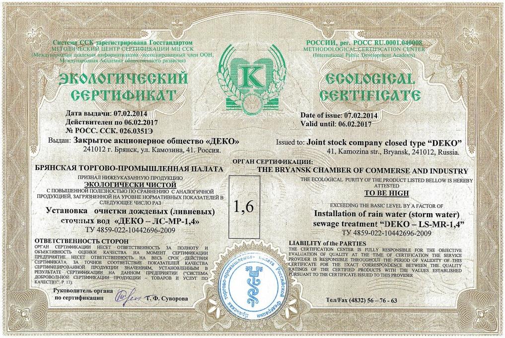
Ecological certificate
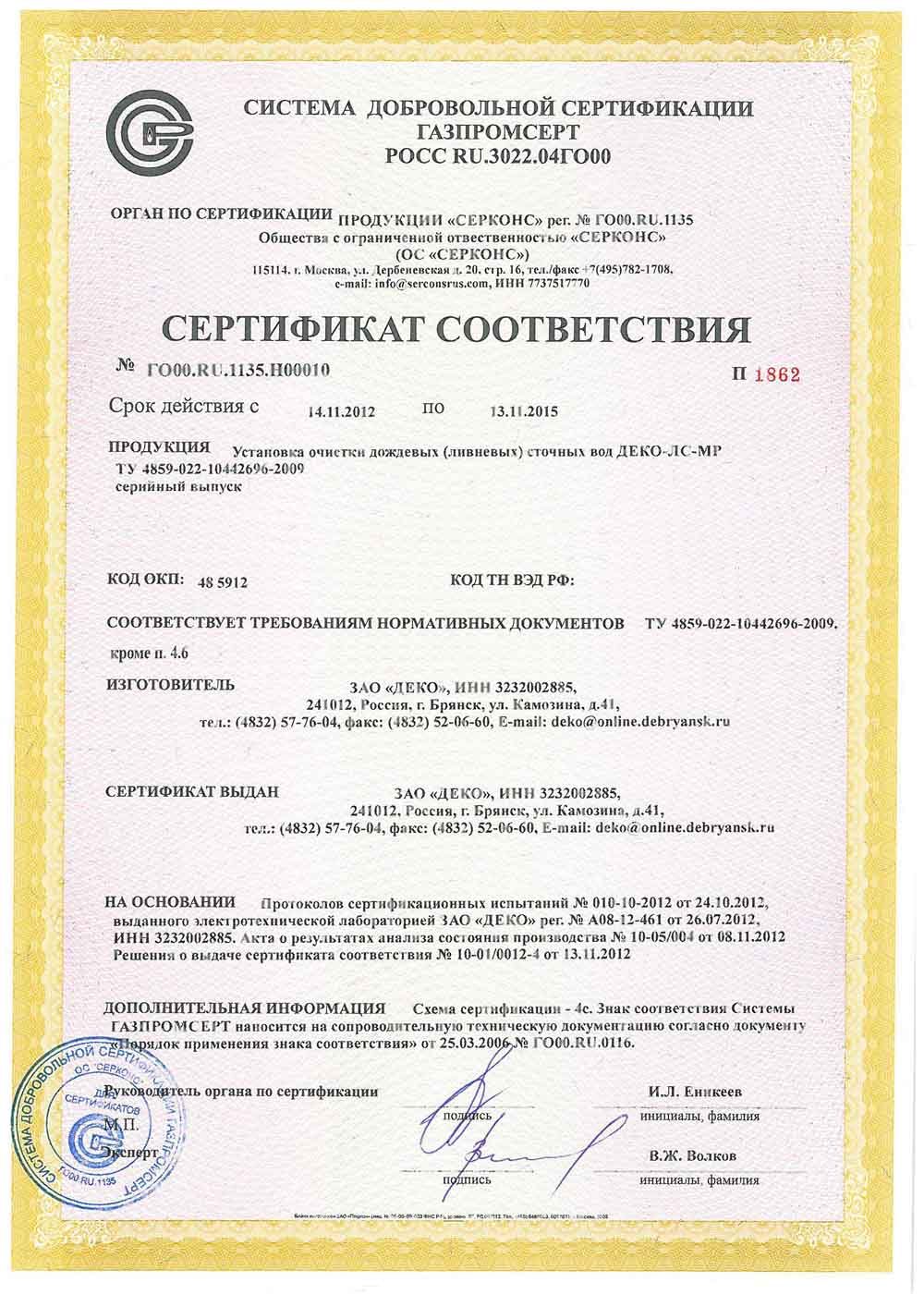
Certificate of conformance
Теl./fax: (4832) 56-59-38
(4832) 52-19-33
(4832) 57-76-04
Company "ДЕКО", Brjansk
Wastewater treatment
and gas emissions
- Eng


- Rus